zBoost
zBoost YX052 Wide-band Omni-directional Ceiling-mount Indoor Antenna (2 dBi PCS / 1 dBi CEL / 1 dBi LTE)
zBoost YX052 Wide-band Omni-directional Ceiling-mount Indoor Antenna (2 dBi PCS / 1 dBi CEL / 1 dBi LTE)
Couldn't load pickup availability
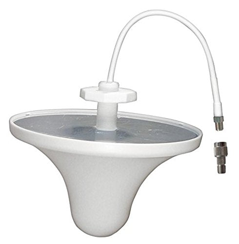
The directions below will assist you in the installation of the YX052 ceiling mount Omni-directional indoor antenna. The antenna provides enhanced performance for the zBoost cell phone signal booster and is compatible with consumer and commercial zBoost products.
The YX052 antenna provides enhanced signal strength in all directions (omni-directional) from the antenna. The antenna should be located near the center of the area where improved signal strength is desired. The antenna requires a length of coax cable (not included) to be able to connect to the Base Unit. It is recommended to use 15Â of RG-6 cable, Part YX030-15W
Specifications:
 Frequencies: 700  2500 MHz
 Gain: 1 -2 dBi
 Beamwidth: Omni directional
 Polarization: Vertical
 Dimensions: 6.5ÂL x 6.5ÂW x 3.35ÂH
 Weight: 0.77 lbs
 Connector: F Female
 Mounting: Ceiling mount in ¾ diameter hole
 Return Loss: >14 dB
Installation Guide:
1) Drill a ¾ diameter (19 mm) hole in the ceiling where the antenna is to be mounted.
2) Route the RF cable and threaded mount of the antenna through the hole from the room side as shown.
3) Attach the plastic nut over the threaded section extending through the ceiling and hand-tighten the nut. Excessive force can damage the threaded mount of the ntenna.
4) Connect the RF cable of the antenna to a 15Â coax extension cable (not provided). Then, using the provided TNC-F adapter, connect the coax to the Base Unit.